Decomposition of basic SVG shapes to paths
There are 6 basic SVG shapes:
<circle><ellipse><line><polygon><polyline><rect>
These can be decomposed and converted into path elements (<path>) without any visually perceivable loss. Since basic shapes can all be converted into paths, doing so reduces variability in the training dataset and should help the learning algorithm.
Open question
Is it possible to keep these basic SVG shapes as part of the feature vector? Would this help with ensuring that circles remain circles and are not just approximated by squiggly lines in the SVG output? A circle will always be a circle – no matter how parameters are chosen. However, two elliptical arcs initially forming a circle can lose the circular shape depending on the chosen parameters.
Unsupported basic SVG shape |
Explanation |
Replacement |
|---|---|---|
A circle defined by the center point (x,y) and a radius. |
Can be transformed to a path using two or four Elliptical Arc commands, which themselves can be converted to Cubic Bézier curves. |
|
An ellipse defined by 4 parameters, the ellipses position (x,y) and the radius on the x axis and the radius on the y axis |
Can be transformed to a path using four Elliptical Arc commands, which themselves can be converted to Cubic Bézier curves. |
|
A straight line defined by the start point (x1, y1) and the end point (x2, y2) |
Can be converted into a path using the LineTo command |
|
A closed shape consisting of a set of connected straight line segments. A polygon is defined by a sequence of points; the last point is connected to the first point. |
Can be converted into a path using the LineTo command. |
|
A shape consisting of a sequence of connected traight line segments. As opposed to the |
Can be converted into a path using the LineTo command. |
|
A rectangle defined by the position of the upper left corner (x, y), its width and height (and optionally the radius for rounded corners) |
Can be converted into a path using the LineTo command. Please note that DeepSVG may overlook the option of rounded corners at this point. |
Preprocessing using SVGO
SVGO’s convertShapeToPath can perform the following conversions out of the box:
convert rect to path
convert line to path
convert polyline to path
convert polygon to path
optionally convert circle to MAAZ (two half-circles)
optionally covert ellipse to MAAZ
Warning
The optional boolean parameter convertArcs of convertShapeToPath appears to be a misnomer or at least misleading. This does not mean that convertShapeToPath converts arc commands (by approximating them using cubic Bézier curves) but the parameter merely defines if circles and ellipses shall be converted to MAAZ paths or not.
The corresponding configuration in a svgo_config.yml file is:
  - convertShapeToPath:
      convertArcs: true
Warning
convertShapeToPath does not check if a rectangle has rounded corners. Rounded corners can be specified by the rx and/or ry attributes of the <rect> element. convertShapeToPath will just treat these as if they were normal rectangles with 90° angles.
(3.1) Decomposition of circles
The decomposition of circles into four or just two elliptical arc curves is possible without any loss in visual quality.
4 quarter-circles represented by elliptical arcs
As stated in the SVG standards for a circle, …
mathematically, a ‘circle’ element is mapped to an equivalent ‘path’ element that consists of four elliptical arc segments, each covering a quarter of the circle. The path begins at the “3 o’clock” point on the radius and proceeds in a clock-wise direction (before any transformations). The rx and ry parameters to the arc commands are both equal to the used value of the r property, after conversion to local user units, while the x-axis-rotation, the large-arc-flag, and the sweep-flag are all set to zero. The coordinates are computed as follows, where cx, cy, and r are the used values of the equivalent properties, converted to user units:
A move-to command to the point cx+r,cy;
arc to cx,cy+r;
arc to cx-r,cy;
arc to cx,cy-r;
arc with a segment-completing close path operation [not supported yet?].
DeepSVG implements a decomposition using 4 elliptical arcs. The example from the paper is a circle defined as follows:
<circle
  cx="1"
  cy="1"
  r="1"
/>
So, this is a circle around the center point \((1, 1)\) with a radius of 1 (and, thus, a width of 2). This circle gets translated a MoveTo command and four elliptical arc curves followed by a closing command.
<path
  d="
    M1,0
    A1,1 0 0 1 2,1
    A1,1 0 0 1 1,2
    A1,1 0 0 1 0,1
    A1,1 0 0 1 1,0
    z
  "
/>
The first arc starts at the top point of the circle (remember that \(y=0\) is the top in the SVG coordinate system) and draws a quarter circle in a clockwise direction to the absolute point \((2, 1)\).
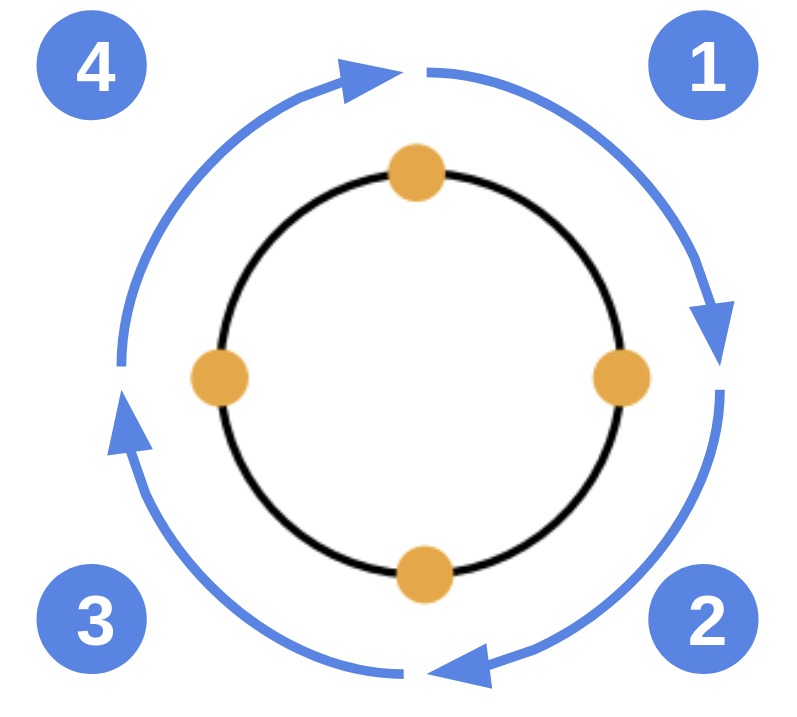
Fig. 72 Circle decomposition in DeepSVG using four elliptical arc curves; center figure from Appendix of the DeepSVG paper
2 half-circles represented by elliptical arcs
The SVG decomposition of circles to paths (and vice versa) has also been covered by this article by the smashingmagazine.com.
<svg
   xmlns="http://www.w3.org/2000/svg"
   width="100"
   height="100"
   version="1.1">

    <circle cx="50" cy="50" r="25"/>

</svg>
The option for circle decomposition proposed in the article is to use a MoveTo command followed by two half-circle elliptical arc segments, each describing a half-circle. SVGO also uses two arcs describing half-circles.
<path
  d="
    M 25, 50
    a 25,25 0 1,1 50,0
    a 25,25 0 1,1 -50,0
  "
/>
Let’s assume, we want to replace had a center point \(C\) at (50, 50) and a radius \(r\) of 25. Since we no longer define a circle but a a path, we need to define a new starting point for the overall shape on the circles outline. One possible way is to start at the leftmost point of the circle. To get there, we can use the same y-coordinate as the center point. The x-coordinate is the center point’s x-coordinate minus the radius.
So, as a first command, we move the pen to the absolute position \((x, y) = (C_x - r, C_y) = (50 - 25, 50) = (25, 50)\). So the command is: M 25, 50.
Then we can start to draw the first elliptical arc curve using a relative positioning:
The parameters of the first arc 25,25 0 1,1 50,0 mean the following:
25: The relative X radius of the arc;25: The relative Y radius of the arc;0: angle in degrees (rotation of the ellipse relative to the x axis)1: large-arc-flag, a binary variable indicating which arc shall be drawn: the large (1) or the small one (0)1: sweep-flag, a binary variable indicating which arc shall be drawn: a clockwise turning arc (1) or the counter-clockwise turning one (0)50: The ending X coordinate (relative) of the arc0: The ending Y coordinate (relative) of the arc
The radius of the arc along either dimension needs to be the same as the radius of the circle we replace. These are the first two parameters.
The last two parameters define the end point of our arc. Our current position (25, 50), the leftmost point of the circle. We want draw a half-circle, which means we want to end at the rightmost point on the other side of the cirle. That point is on the same vertical position but the circle’s width (2 x the radius), i.e. 50, further to the right, i.e. \((25 + 50, 50 + 0) = (75, 50)\).
The ellipse is not rotated relative to the x axis. So, the third parameter is set to 0 (degrees).
The information so far is not enough to know which of the possible arcs need to be drawn. The two remaining binary flags provide that specification. The first flag has no practical effect. The second flag, however, defines that the arc shall be drawn in clockwise direction from our current point. Which means that the first arc describes the upper half-circle.
A closing z command may also be required but was not used in the article – likely since it does not impact the visual representation.
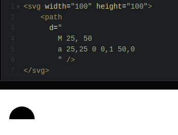
Fig. 73 Only the upper half-circle defined in SVG using an elliptical arc command; code shown on top; resulting half-circle at the bottom; visualized using codepen.io
Adding a second elliptical arc to describe the lower half-circle completes the circle. Note that only the end point needs to be adjusted. We want to end up 50 pixels to the left again and at the same vertical position.
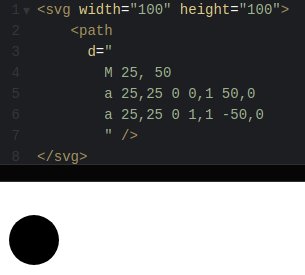
Fig. 74 Full circle described by two half-circles formed by elliptical arc curves; visualized using codepen.io
SVGO uses the following (Javascript) logic for a circle with center point \((cx, cy)\) and radius \(r\). SVGO first moves to top point of the circle.
const pathData =
  [
    { command: 'M', args: [cx, cy - r] },
    { command: 'A', args: [r, r, 0, 1, 0, cx, cy + r] },
    { command: 'A', args: [r, r, 0, 1, 0, cx, cy - r] },
    { command: 'z', args: [] },
  ];
(3.2) Decomposition of ellipses
SVGO uses the following (Javascript) logic for an ellipse with the position \((cx, cy)\) and the radius of the ellipse on the x axis \(rx\) and on the y axis \(ry\). Null values are replacec by a zero default value.
const pathData =
  [
    { command: 'M', args: [cx, cy - ry] },
    { command: 'A', args: [rx, ry, 0, 1, 0, cx, cy + ry] },
    { command: 'A', args: [rx, ry, 0, 1, 0, cx, cy - ry] },
    { command: 'z', args: [] },
  ];
(3.3) Decomposition of lines
Lines, defined by a start point and an end point, can be trivially decomposed to a MoveTo command followed by a single LineTo command.
The following line defines a straight line from \((x_1, y_1)=(0, 0)\) to \((x_2, y_2)=(1, 1)\).
<line
  x1="0"
  x2="1"
  y1="0"
  y2="1"
/>
To decompose the basic shape, we can move to the starting position and then use the end point as parameter for the LineTo command:
<path
  d=
    "
      M 0,0
      L 1,1
    "
/>
SVGO uses the following (Javascript) logic for a line with start point \((x1, y1)\) and end point \((x2, y2)\):
const pathData =
  [
    { command: 'M', args: [x1, y1] },
    { command: 'L', args: [x2, y2] },
  ];
(3.4) Decomposition of polygons
Polygons are just closed polylines and can also trivially be decomposed using a MoveTo command followed by a sequence of LineTo commands.
The following polygon is defined by three points \((0, 0)\) (top left), \((1, 0)\) (top right), and \((1, 1)\) (bottom right). The shape gets closed by definition.
<polygon
  points=
    "
      0, 0
      1, 0
      1, 1
    "
/>
The polygon can get replaced by the following path:
<path
  d=
    "
      M 0,0
      L 1,0
      L 1,1
      z
    "
/>
We first move to the starting position \((0, 0)\), then we create lines to the second point and the third point and close the path using the z command.
SVGO uses the following (Javascript) logic for a polygon:
const coords = (node.attributes.points.match(regNumber) || []).map(Number);
const pathData = [];
for (let i = 0; i < coords.length; i += 2) {
  pathData.push({
    command: i === 0 ? 'M' : 'L',
    args: coords.slice(i, i + 2),
  });
}
if (node.name === 'polygon') {
  pathData.push({ command: 'z', args: [] });
}
The first command is always M, followed by a sequence of L commands. If the shape is a Polygon, a z command is added in the last step to close the shape.
(3.5) Decomposition of polyline
Polylines are just sequences of straight lines and are not automatically closed.
Thus, they can be replaced the same way as polygons – just without the closing command z.
<polyline
  points=
    "
      0, 0
      1, 0
      1, 1
    "
/>
This is the replacement path data:
<path
  d=
    "
      M 0,0
      L 1,0
      L 1,1
    "
/>
SVGO uses the following (Javascript) logic for a polyline:
const coords = (node.attributes.points.match(regNumber) || []).map(Number);
const pathData = [];
for (let i = 0; i < coords.length; i += 2) {
  pathData.push({
    command: i === 0 ? 'M' : 'L',
    args: coords.slice(i, i + 2),
  });
}
The first command is always M, followed by a sequence of L commands.
(3.6) Decomposition of rectangles
Rectangles can also trivially be converted into a sequence of straight lines by using a MoveTo command, three or four LineTo commands and a closing command z.
<rect
  x="0"
  y="0"
  width="1"
  height="1"
/>
The \((x, y)\) parameters of a rectangle defines the position of the upper left corner. Thus, this is the replacement path data:
<path
  d=
    "
      M 0,0
      L 1,0
      L 1,1
      L 0,1
      L 0,0
      z
    "
/>
Is is also possible to just use three LineTo commands since the closing command z would form a straight line anyways and needs to connect the last and the first point:
<path
  d=
    "
      M 0,0
      L 1,0
      L 1,1
      L 0,1
      z
    "
/>
SVGO uses the following (Javascript) logic for a rectangle with position (of the upper left corner) \((x, y)\), width and height:
const pathData =
  [
    { command: 'M', args: [x, y] },
    { command: 'H', args: [x + width] },
    { command: 'V', args: [y + height] },
    { command: 'H', args: [x] },
    { command: 'z', args: [] },
  ];
The H and V commands would then still need to be replaced by general L commands.
Rectangles with rounded corners
The SVG format allows for rectangles with rounded corners. Rounded corners can be defined by adding / altering the horizontal and/or the vertical corner radius parameters \(rx\) and \(ry\) of the <rect> element. If only one radius parameter is provided, the other is assumed to be equal. This results in a corner looking like a circle segment. If one radius is different than the other, this is not the case and one corner side is flatter than the other.
Please note that the attribute stroke-linejoin="round" achieves a similar result of rounding corners but needs to be treated separately.
Rectangles with rounded corners have not been considered by any of the published papers. Thus, these rectangles would have been represented with normal corners.
Converting rectangles with rounded corners to paths is more complicated.